H2: Logic Circuits#
Time Estimate1-2 hours Grade Impact1% DueSep 14 @ 12pm
Objective
Demonstrate an understanding of logic circuits.
Helpful Tip
The free CircuiTikZ Designer provides an intuitive GUI that can help you typeset beautiful circuit diagrams in CircuiTikZ, a professional way to typeset circuits in $\LaTeX$ documents. It’s what I used to generate the figures on this page. Circuit simulators are also helpful, there is a list on the Resources page.Also, WaveDrom is an easy place to generate timing diagrams. It’s what I used to generate diagrams for this assignment.
Show your work#
You must show all steps of your work for full credit. While calculators can perform these conversions, demonstrating your process ensures understanding and mastery of the concepts.
Exercises#
-
Draw a circuit that evaluates the formula $\lnot(A \lor B) \land (C \land \lnot D) = E$.
-
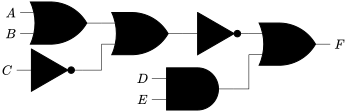
Write a formula that corresponds to the following circuit:
-
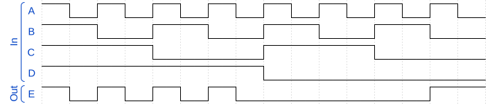
Write a formula that corresponds to the following timing diagram:
-
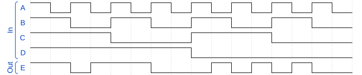
Draw a circuit that corresponds to the following timing diagram:
-
Complete a truth table for $F = (\lnot A \land B \lor C) \land (D \lor \lnot E) \lor (A \land \lnot D)$.
-
Complete a truth table for $G = (A \lor \lnot B) \land (C \lor D) \land (\lnot A \lor \lnot C)$.
-
Complete a timing diagram for $E = (\lnot A \lor B \land C) \lor (D \land \lnot B) \land (\lnot B \lor A)$.
-
Draw a circuit that evaluates $E = (A \land B) \lor (\lnot C \land D) \lor (B \land \lnot D)$.
-
Design your own circuit! Write a logical formula that your circuit will evaluate. It must contain at least 4 inputs and 1 output. Draw and label a circuit diagram that corresponds to your formula. Construct a truth table for your formula, showing all possible input combinations and the corresponding output. Create a timing diagram that illustrates the behavior of your circuit for interesting input combinations.
-
Try to draw a circuit that evaluates $A = (\lnot A \land B)$. Do you think it is possible to construct this circuit using only AND, OR, and NOT gates? Why or why not? If it is not possible, what would make it possible?