L18: Multiplexers#
Let’s practice Boolean algebra!
Objective
Practice usage of theorems 5-17 of Boolean algebra.
Before the Lecture#
Required Textbook Reading:
- 4.1 (Multiplexers)
Optional Supplemental Instruction:
- Multiplexer – Wikipedia
- Multiplexers: How Do They Work? – Electrical 4 U
Modular Building Blocks#
Circuits can be built using a variety of modular building blocks. These building blocks can be combined in different ways to create more complex circuits, and they can save time and effort in the design process. In this lecture, we will focus on multiplexers (MUXes).
Specification#
What is a Multiplexer?#
A multiplexer (MUX) is a combinational logic circuit that selects one of several input signals and forwards it to a single output line. It acts as a digital switch, routing data from one of many input channels to a single output based on control signals called select lines or selector lines.
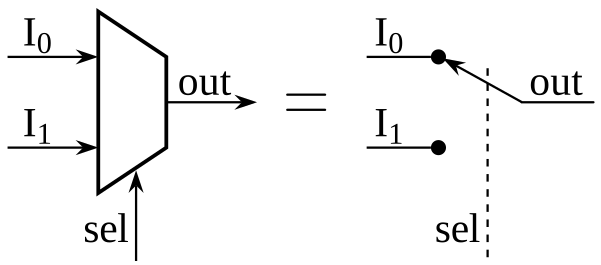 By CaesarIII - Own work, CC BY-SA 3.0, Link
Key Characteristics#
- Multiple Inputs: A multiplexer has $2^n$ data inputs, where $n$ is the number of select lines
- Select Lines: Control which input is routed to the output. An $n$-bit select signal can address $2^n$ different inputs
- Single Output: All selected inputs are combined into one output line
- Combinational Logic: The output is determined solely by the current input and select signal values (no memory)
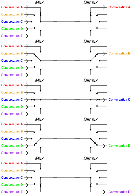 By Tony R. Kuphaldt - Socratic Electronics website : [1], CC BY 1.0, Link
How It Works#
The multiplexer uses the select lines as an address to choose which input data line to connect to the output. For example:
- A 2-to-1 MUX requires 1 select line and has 2 inputs
- A 4-to-1 MUX requires 2 select lines and has 4 inputs
- An 8-to-1 MUX requires 3 select lines and has 8 inputs
Boolean Expression#
For a 2-to-1 multiplexer with inputs $I_0$ and $I_1$, and select line $S$:
$$Y = \overline{S} \cdot I_0 + S \cdot I_1$$
Applications#
Multiplexers are widely used in:
- Data routing and switching
- Channel selection in communication systems
- Analog signal selection (analog multiplexers)
- Implementing complex logic functions
- Address decoding in memory systems
Synthesis#
You can implement a multiplexer using basic logic gates (AND, OR, NOT). The design involves creating AND gates for each input line, controlled by the select lines, and then combining their outputs with an OR gate to produce the final output.
Discussion & Practice
As a class, let’s work through Examples 4.2 – 4.6 in the textbook.