L0: Course Introduction#
Welcome to this course.
Objective
(a) Establish expectations and responsibilities regarding this course, and
(b) Understand the context for this course’s material.
Before the Lecture#
- Read the following:
- Start Here
- Course Policies
- Official Syllabus (on Canvas)
- Textbook sections 1.1–1.3 (Introductory Materials)
- Complete the Action Items.
I will not insult your intelligence by covering these tasks extensively in-class. If you have questions, please ask them during lecture or contact me directly (via email or Canvas message).
Setting Expectations#
For most students, this is a challenging course, but it is also engaging and rewarding. It will require consistent effort and engagement to master foundational concepts. This is an excellent opportunity to invest in yourself to deepen your critical thinking and problem-solving skills. You are expected to actively participate in lectures, complete assignments on time, and collaborate with peers.
While I have put a great deal of effort into designing a course that maximizes your opportunities to learn, it is your responsibility to use any resources at your disposal to learn this course’s content. By the end of the course, you should be able to design, analyze, and implement basic digital circuits, preparing you for more advanced topics in the field.
Read more about expectations on the Start Here page and the Official Syllabus on Canvas.
Supplies#
You will need the following supplies:
- Textbook: Fundamentals of Digital Logic with Verilog Design, 3rd Edition by Stephen Brown and Zvonko Vranesic. ISBN 9780073380544
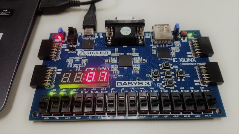
- FPGA Board: Digilent Basys 3 available via the ECE Store.
- USB Cable: Required to connect the FPGA board to the computer.
- Lab Notebook: A notebook (digital or physical) to document your lab work.
Ensure you have these items ready before Lab1 (which is next week). If you have any questions about acquiring these supplies, please reach out. You can probably borrow some of these supplies for a few days if you’re waiting on shipping.
Course Organization#
To maximize learning opportunities, this course approaches each important topic from several angles. The full outline and schedule of the course are available. The basic heirarchy of the course is as follows:
- Modules are the top-level division of course material. Each module takes (on average) two weeks.
- Lectures introduce the concepts of the course at a high level.
- Readings give an in-depth description of topics discussed in lectures.
- Homeworks are low-stakes practice to reinforce students’ understanding of course material.
- Quizzes are low-stakes evaluations of students’ understanding of lectures and readings.
- Labs are medium-stakes and bring theoretical concepts into the real world.
- Assessments are high-stakes evaluations of students’ undertstanding of multiple modules.
Grades#
See Course Policies for detailed information about grading. tl;dr:
- You can resubmit two assignments (homework, quiz, or lab) to reclaim up to 90% of lost points!
- Your first late penalty for homework, quizzes, and labs is waived!
- You have 3 work days after grades post to challenge a grade.
- Late assignments have time-based penalties, and late assessments are not accepted.
---
config:
    theme: 'base'
    treemap:
        valueFormat: '1.0%'
---
treemap-beta
"High Stakes"
        "Midterm": 0.15
        "Final": 0.25
"Medium Stakes"
        "Labs": 0.30001
"Low Stakes"
        "Quizzes": 0.10
        "Homework": 0.15
"Participation 5%": 0.05Assessments#
- No traditional exams; competency is demonstrated through flexible alternatives.
- Students must complete one midterm and one final assessment.
- Assessments are proposed by students and approved by the instructor.
- See Assessment Ideas for inspiration.
Digital Abstraction#
Digital systems process and represent information using discrete digits, typically in binary form (0 and 1). Unlike analog systems, which handle continuous signals, digital systems operate on distinct states, making them more robust to noise and easier to manipulate computationally.
In modern digital systems, we focus on two simple states: “on” (1) and “off” (0), instead of worrying about all the tiny details of how electricity flows. View a demo of Digital Abstraction on Desmos. In this demo, the blue sine wave represents a continuous signal. The orange line represents the digital abstraction: the output is 1 if the continuous signal exceeds 0.5, and 0 otherwise.
Here’s what makes digital abstraction so helpful:
- Binary Thinking: Everything is either 1 or 0, like flipping a light switch on or off. We can deal with two states at a time rather than the infinite number of real numbers.
- Clear Rules: We decide what counts as “on” or “off,” so small changes or noise don’t cause problems.
- Predictable: We can focus on how the system behaves, making it easier to design and fix.
This simple way of thinking is the foundation of all modern technology, from the apps on your phone to the processors in supercomputers.
Digital Hardware#
Digital hardware forms the backbone of modern computing systems. At its core, this course focuses on the design and analysis of logic circuits, which are the fundamental building blocks of digital systems. Logic circuits process binary information, enabling the execution of complex tasks in computers, smartphones, and countless other devices.
Throughout this course, you will explore the principles and techniques used to design these circuits. You will learn how to represent logical operations using Boolean algebra, implement them with gates, and analyze their behavior. By understanding these foundational concepts, you will gain the skills necessary to create efficient and reliable digital systems.
Since the 1960s, the evolution of digital hardware has been closely tied to Moore’s Law, which predicts the doubling of transistors on a chip approximately every two years. This exponential growth has driven remarkable advancements in computational power, efficiency, and miniaturization.
Standard Chips#
Standard chips are pre-designed and mass-produced components that perform specific functions. These chips are widely used in digital systems due to their reliability, cost-effectiveness, and ease of integration. Examples include logic gates, multiplexers, decoders, and memory units. Standard chips are ideal for applications where the required functionality is common and does not need customization.
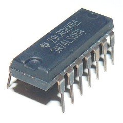
Image: RetroEditor, CC BY 4.0, via Wikimedia Commons

Programmable Logic Devices#
Programmable Logic Devices (PLDs) are versatile components that can be configured by the user to perform a wide range of digital functions. Unlike standard chips, PLDs allow designers to implement custom logic without the need for manufacturing new hardware. Examples of PLDs include Field-Programmable Gate Arrays (FPGAs) and Complex Programmable Logic Devices (CPLDs). These devices are particularly useful in prototyping, research, and applications requiring flexibility and reconfigurability.
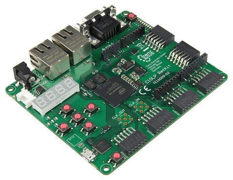
Image: Antti Lukats, CC0, via Wikimedia Commons

Custom Chips#
Custom chips, or Application-Specific Integrated Circuits (ASICs), are designed and manufactured to meet the specific requirements of a particular application. These chips offer high performance, efficiency, and optimization for their intended use but come with higher development costs and longer design cycles. Custom chips are commonly used in industries such as telecommunications, automotive, and consumer electronics, where specialized functionality and performance are critical.
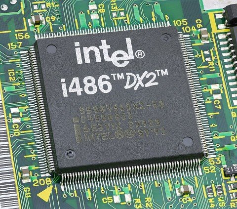
Image: Mister rf, CC BY-SA 4.0, via Wikimedia Commons

Discussion
In what scenarios would each circuit type be most appropriate?
The Design Process#
The design process in digital systems involves a structured approach to creating functional and efficient circuits. It typically includes the following steps:
-
Specification: Define the requirements and constraints of the system, including functionality, performance, and cost.
-
Design Entry: Represent the design using tools such as schematic diagrams, hardware description languages (HDLs), or truth tables.
-
Simulation: Verify the design’s functionality and performance using simulation tools to ensure it meets the specifications.
-
Implementation: Map the design onto the target hardware, such as an FPGA or ASIC, and optimize it for area, speed, and power consumption.
-
Testing and Debugging: Test the physical implementation to identify and fix any issues, ensuring the design operates as intended in real-world conditions.
-
Iteration: Refine the design based on testing results, repeating the process as necessary to achieve the desired outcome.
This iterative process ensures that the final design is robust, efficient, and meets all specified requirements.
The following flowchart (similar to Figure 1.3 in the textbook) represents a typical CAD workflow.
---
title: "Typical CAD Workflow"
config:
    theme: 'default'
---
flowchart TD
    A([Design conception]) --> DESIGN-ENTRY
    subgraph DESIGN-ENTRY [Design Entry]
        DE1([Schematic Capture])
        DE2([HDL Specification])
    end
    DESIGN-ENTRY --> B
    B[Synthesis] --> C[Functional Simulation]
    C --> D{Design Correct?}
    D -->|Yes| E
    D -->|No| DESIGN-ENTRY
    E[Physical Design] --> F[Timing Simulation]
    F --> G{Timing Requirements Met?}
    G -->|Yes| H
    G -->|No| DESIGN-ENTRY
    H[Chip Configuration]
Structure of a Computer#
A computer is a complex system composed of several interconnected modules, each responsible for specific tasks. This modular design allows for easier development, troubleshooting, and upgrading of individual components without affecting the entire system. The modular design ensures that each component can be developed and optimized independently, contributing to the overall functionality and performance of the computer.
Modular Design#
Modular design is all about breaking a system into smaller, manageable pieces, or modules, each with its own specific job. This approach makes systems easier to build, test, and maintain. Here’s why it’s so valuable:
- Scalability: You can swap out or add a module without redoing the whole system.
- Flexibility: Modules can be reused in other projects, saving time and effort.
- Maintainability: If something breaks, it’s easier to pinpoint and fix the problem in a specific module.
- Collaboration: Teams can work on different modules at the same time, speeding up development.
- Customization: You can mix and match modules to create a system that fits your exact needs.
Discussion
What are some real-world examples of modular design in technology, and how do they demonstrate the benefits of scalability, flexibility, and maintainability?
Can you think of any potential drawbacks or challenges associated with modular design in complex systems?